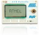
My first program, Blinky, from the “C Programming for Microcontrollers” book has been downloaded to my Butterfly ATMega169 and works. The program cycles through 8 LEDs, turning one LED on at a time. It looks like the Cylon robots (old school – or the newer Cylon Centurions from the new series) robots. (Or the original KITT from “Knight Rider”.)
I had a problem initially with downloading the “hex” file to the Butterfly. It appeared to be the serial port… ahhhh, serial ports. So, if you get the Butterfly++ Mini-Kit, you get a DB-9 female connector and some wire. The “Butterfly++ Mini-Kit Assembly Instructions”, and the book, instruct that you are to wire the DB-9 connector to certain holes on the Butterfly. The instructions indicate that you cross the transmit and receive lines from the Butterfly to the connector. Okay, all is good… so far.
It is very hard to find a serial cable now: USB rules. But I did find a USB-Serial adapter at Best Buy. One end is a USB connector and the other end is a DB-9 male connector. I installed the driver, for Windows XP, and installed the cable. It installed like a charm as “COM5”. I was able to use the terminal program provided on the CD with the book and use “COM5” and communicate with the built-in Butterfly program to set my name for the “name tag” function of the factory-programmed Butterfly.
But then when I used the provided AVR Studio to try and download the Blinky program to the Butterfly, AVR Studio couldn’t find a suitable device. Hmm. It appeared the AVR Studio provided on the book’s CD wasn’t working with the USB serial device. I even tried upgrading to the latest AVR Studio downloaded from the Atmel site. It still wouldn’t program.
I did have a “real” serial port on my computer, which is a DB-9 male connector. But I couldn’t find a DB-9 M-F connector in my collection of cables. I had null modem DB-9 F-F and DB-9 M-M (null modem cables have the transmit and receive links cross-linked). Then I thought, wait! The Butterfly has a DB-9 female connection and the computer has a DB-9 male connector; just hook them together. The problem is the Butterly DB-9 female connector is connected to the Butterfly with about 2.5 inches of wire. So it took a bunch of rearranging to get the Butterfly close enough to the serial port on the computer, which is in the back of the computer. But I was able to get the Butterfly, the power supply, and the breadboard with the LEDs for the Blinky project close enough. Now, with the Butterfly directly connected to “COM1”, the AVR Studio found the device. I was able to download and program the Blinky.hex file. After successfully downloading to the Butterfly and cycling the power to the Butterfly (and moving the joystick “up”), Blinky started up and blinked the LEDs, sweeping back and forth.
So it appears that I need a DB-9 M-F “straight through” serial cable. (I have seen this type of cable referred to as an “extension” serial cable too. No wonder everyone likes USB better-it just seems to work, but it is more complex at the signal and component level.) I was able to find at Cables for Less a six foot DB-9 male to female cable for $1.89. I ordered it. With shipping the total came to $8.48. Hopefully it will come soon so that I can get the Butterfly out from behind my computer. But at least I have successfully tested the ability to program the Butterfly.
(I think that there is some way to download the hex file using avrdude instead of the AVR Studio. This may allow the USB-Serial adapter cable to work on “COM5”. But I haven’t had a chance to try that yet.)
